|
These are custom designed and
manufactured stainless steel replacement tremolo arms
for the 1983-1984 Elite Strat® with the
Freeflyte or System II tremolo bridge assembly. The
Strat's from this era are often referred to as Dan Smith
Strat's.
We are fabricating these tremolo arms
using an original Fender® 6" length Elite Strat® tremolo
arm as the production template which allows us to create
a correct replica in design, length and bend angles. The
two shorter lengths we offer are specific to our
reproductions only and are for those that don't want the
full 6" length tremolo arm, these shorter lengths were
never offered by Fender.
These reproduction tremolo arms are
the pop-in style with a small cross-pin which rests
into the small groove in the tremolo arm receptacle/bushing on the bridge
which
allows you to adjust the rotational friction of
the tremolo arm.
As illustrated below and to the right
we illustrate the two styles of tremolo bridges that
were found on
the models of Strat® that accept these tremolo arms. One
of the
bridges is the
deluxe version and the other is the basic or standard
version and both bridges accept this same type of tremolo arm
offered here.
To effectively use these tremolo arms your bridge should be setup as
free-floating.
Each of these tremolo arms are
custom fabricated
by hand from precision centerless ground 303 stainless
steel for a fine finish and relative ease of
fabrication. Additionally each of these tremolo arms are
polished to a high-luster finish similar to chrome.
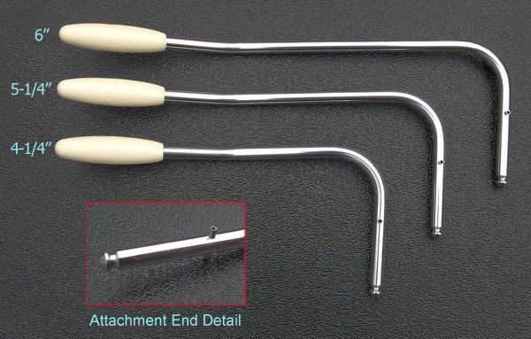
Available
in three lengths:
- 6" Standard Length.
- 5¼"
Intermediate Length.
- 4¼" Short Gilmour Length.
Available in right or
left handed.
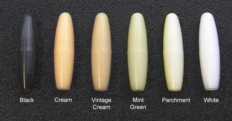
As depicted to the right, we offer
six different colored plastic tips to choose from. The
choices are black, cream, vintage cream, mint green,
parchment or white.
You may also
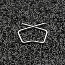
need the tremolo arm retaining clip shown below. Click
on the image for details.
Important Information About
These Tremolo Arms
If you don't know if your bridge is
missing the tremolo arm retaining clip you can look straight down
into the center of the bushing that the tremolo arm
inserts into and at the
bottom about 1" down you would be able to see a small
portion of the retaining clip going across the edge of
the inside of the bushing. In the lower-most photograph
(right) you can see how the retaining clip is installed
and how a small portion of the clip extends out into the
path of internal portion of the bushing. If you don't
see the retaining clip then you will probably want to
include one with your order,
If the tremolo arm retaining clip is
missing a misconception of how this tremolo arm snaps
into place is thought (by some) to be accomplished by the small cross-pin
on the tremolo arm and any attempt to press down harder
on the tremolo arm into the bridges tremolo arm bushing to lock the
arm into place with the cross-pin will only damage the
cross-pin in the tremolo arm,
so don't
do that. The retention of the tremolo arm in the bridge
is accomplished by the machined groove at the tip end of the
tremolo arm which snaps into place with the tremolo arm retaining
clip that is mounted in the bushing on the bridge. The small cross-pin that is installed about 1" up
from the tip of the tremolo arm simply rests in the
groove in the bushing on the top side of the bridge and
this bushing has the ability to be tightened or loosened
in how it rotates to dictate how firm or loose the tremolo arm rotates
because of how the tremolo arm's cross-pin engages this
bushing. The adjustment of the bushing is done from the
underside of the bridge by turning the nut in either
direction to change the rotational friction of the
tremolo arm. It's adjustment is simply a matter of
finger rotational tightness on its nut, there is no need
for any wrench, you will only cause problems if you
tighten it with a wrench. To really
understand how this works it is best to have the bridge
removed and make the adjustments with the bridge in your
hand and it will all become clear to you...
|
Below are the two styles
of bridges that accept these tremolo arms.
Each shown from top
and bottom for reference. One is System II and the
other is the Freeflyte.

Above is an example showing the top
side of the Freeflyte tremolo bridge that we fabricate these
tremolo arms for. Bridge not included in this
item purchase, shown for illustration purposes only to
indicate the type of bridge this tremolo arm is designed
to fit.
Above is an example showing the
bottom side of the Freeflyte tremolo bridge that we fabricate these
tremolo arms for. Bridge not included in this
item purchase, shown for illustration purposes only to
indicate the type of bridge this tremolo arm is designed
to fit.
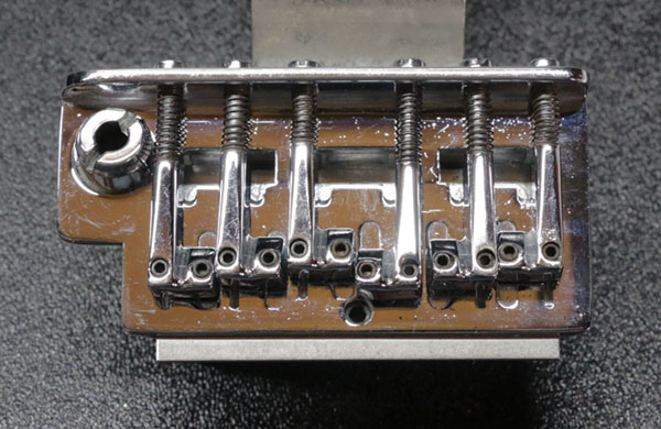
Above is an example showing the top
side of the Freeflyte tremolo bridge that we
fabricate these tremolo arms for. Bridge not included in this
item purchase, shown for illustration purposes only to
indicate the type of bridge this tremolo arm is designed
to fit.
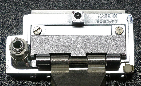
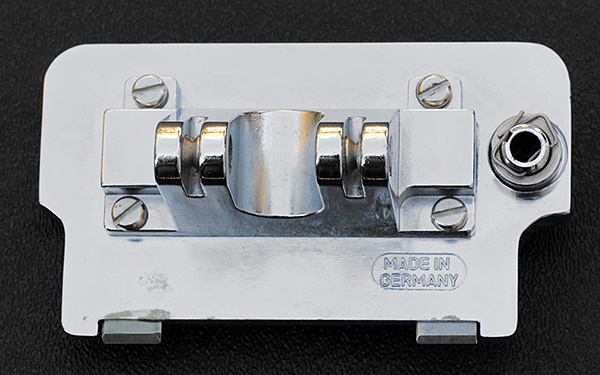
Above is an example showing the back
side of the Freeflyte tremolo bridge that we fabricate these
tremolo arms for. Bridge not included in this
item purchase, shown for illustration purposes only to
indicate the type of bridge this tremolo arm is designed
to fit.
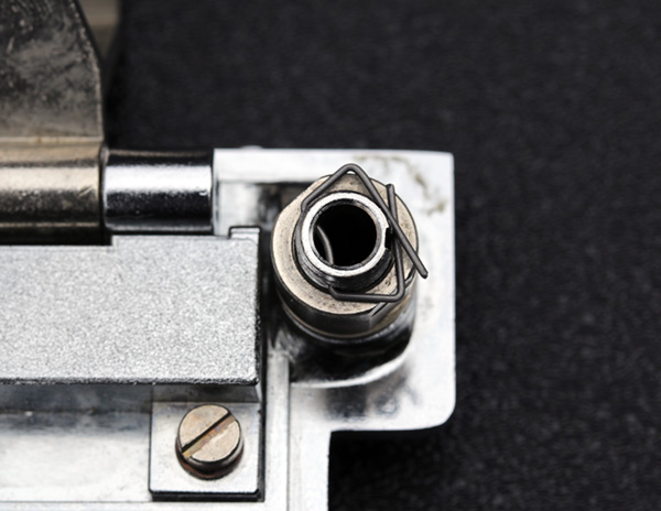
Above is an example showing how the tremolo arm
retaining clip is installed in the bushing and how a
small portion of it extends into the path of the tremolo
arm as it is inserted into the bushing in effect
engaging the groove on the tip end of the tremolo arm
fastening the tremolo arm in place in the bridge. Bridge not included in this
item purchase, shown for illustration purposes only to
indicate the type of bridge this tremolo arm is designed
to fit.
|